An Adressable LED strip is an LED strip where each individual LED can be independently controlled. This is the distinguishing feature of Adressable strips: the ability to program each LED on the strip to to display any color and brightness you want.
Adressable LED strips find versatile application in various domains, including decorative lighting, wearable technology, artistic installations, and dynamic visual displays.
![]()
Getting started
Here are the steps covered in this tutorial:
- Installing Arduino IDE
- Installing FastLED Library
- Setup Arduino
- Download our code examples
- Explore
Needed Materials
- Arduino + USB Cable.
- LED strip (prefferably NEOPIXEL)
- Jumper wires
- External power supply (needed for longer LED strips)
Installing Arduino IDE
To begin, make sure you have the Arduino IDE installed on your computer. If it’s not already installed, you can download it from the official Arduino website at https://www.arduino.cc/en/software.
Installing FastLed Library
Follow this step by step guide FastLED Library. Or see the steps below.
- Open the Arduino IDE on your computer.
- In the Arduino IDE, navigate to the “Sketch” menu located at the top of the screen.
- Within the “Sketch” menu, find and select the “Include Library” submenu.
- A list of available libraries for installation will appear. Scroll down the list until you locate “FastLED” and then click on it.
- A pop-up window containing information about the FastLED library will appear. In this window, you’ll find an “Install” button. Click on this button to initiate the library installation process.
- The Arduino IDE will now proceed to download and install the FastLED library. You’ll be able to track the progress via a status bar displayed on the screen.
- Upon successful completion of the installation, you will receive a notification confirming that the FastLED library has been successfully installed.
- With the library now installed, you can incorporate it into your Arduino sketches. To include the FastLED library in your code, simply add the following line at the beginning of your sketch: #include <FastLED.h>
Setup Arduino
- Prepare the NeoPixel LED Strip:
- Identify the three connectors on your LED strip: +5V (or VCC), Ground (GND), and Data In (DI). If your LED strip has four connectors you need to identify the +5V (or VCC), Ground (GND), Data In (DI), and Clock (CL).
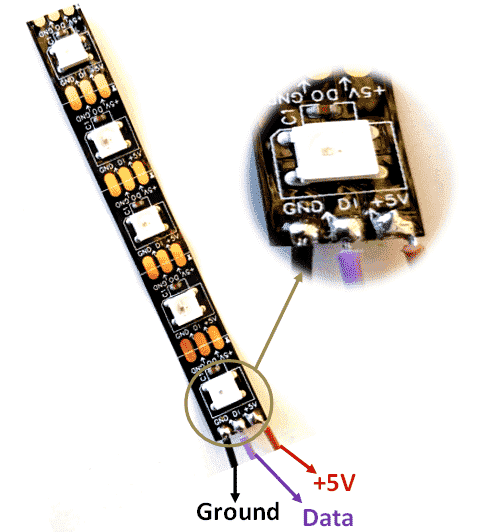
- Identitify the direction of electricity on your LED strip. LED stands for Light Emitting Diode. A diode is an electrical component that allows the flow of current in only one direction. The LED strip will be marked with small arrows to indicate which direction the currrent flows. The arrows should point away from the side where you connect your Wires.
- Connect Power and Ground:
- The LED will have a power connector that is most likely either 5V or 12V. If you are planning on powering the LED strip from your arduino, make sure that you have a 12V LED strip.
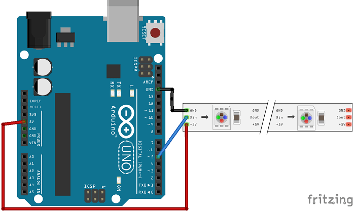
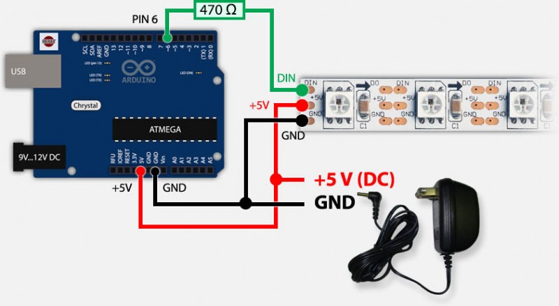
- Connect a jumper wire from the +5V pin on your Arduino to the +5V (VCC) on the LED strip.
- Connect another jumper wire from the Ground (GND) pin on your Arduino to the Ground (GND) on the LED strip.
- This provides power to the LED strip and establishes a common ground reference
- Connect Data In (DI):
- Connect a jumper wire from a digital pin on your Arduino (e.g., Pin 4) to the Data In (DI) on the LED strip.
- Make sure you choose a digital pin that can be used for PWM (Pulse Width Modulation) as NeoPixels require precise timing.
- If your LED strip have a Clock connector this also needs to be connected using a jumper wire from a digital pin on your Arduino (e.g., Pin 5)
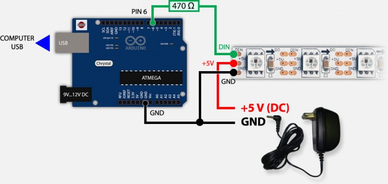
- Power Supply (if needed):
- If you’re using a longer LED strip, A 12V LED strip or multiple strips, it’s essential to provide an external power supply in addition to the Arduino’s power.
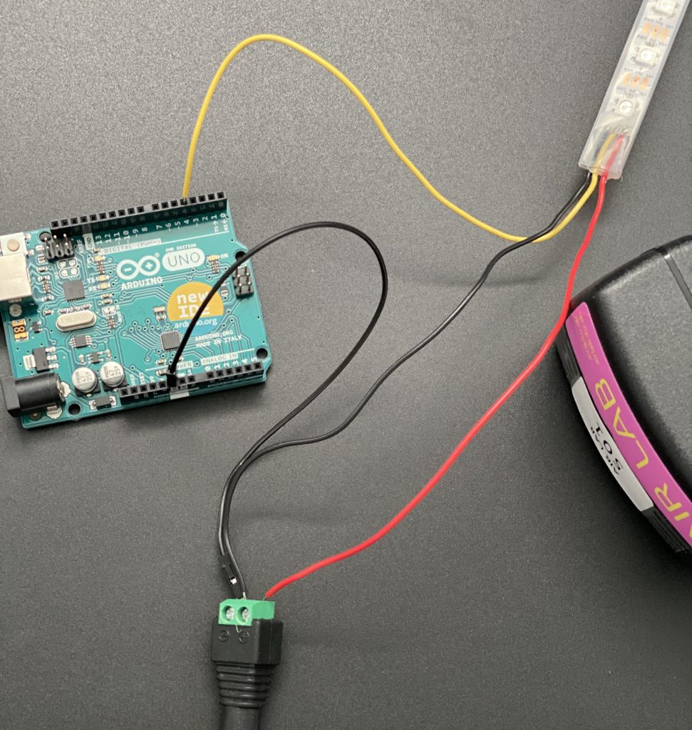
- Connect the +5V and GND wires from the external power supply to the corresponding pins on the LED strip. Ensure the grounds are still connected together with the Arduino.
- This additional power supply ensures that there’s enough current to drive all the LEDs on the strip properly.
- If you want to avoid powering the arduino with USB use the “Stand alone” setup as pictured below
Download test examples (sketches)
To get started you can download some of our test examples from our Git Tutorial Repository. This example uses a 3 connector NEOPixel LED strip.
- Download sketch files: From the NeoPixel tutorial Repository.
- Programming: Write or load an Arduino sketch to control the NeoPixel LEDs. In your code, specify the pin you connected the Data In (DI) wire to (e.g., #define PIN 4).
- Upload Code: Connect your Arduino board to your computer using a USB cable and upload your Arduino sketch to the board. Follow this guide if this is your first time uploading code to a Arduino.
- Testing: Once the code is uploaded, your NeoPixel LEDs should respond to the instructions in your sketch, creating various lighting effects and patterns.
If you are using a 4 wired LED strip follow the steps above and then:
- Add the clock pin: add line to code example:
#define CLOCK_PIN 5Pin number should be the pin number on the Arduino where you have connected the CLOCK_PIN. - In the addLeds function, Change chip type, see overview of different Chipsets below and add CLOCK_PIN argument:
FastLED.addLeds<LED_TYPE, DATA_PIN, CLOCK_PIN COLOR_ORDER>(leds, NUM_LEDS)
Using the FastLED.addLeds function is essential in order to initialize the LED strip. The first argument in the function is LED_TYPE which is used to define which kind of chipset your LED strip use. Some like NEOPIXEL have two names (WS2812B and NEOPIXEL) both are valid as argument. If your LED strip has 4 wires make sure to define the CLOCK_PIN, if you only have 3 wires simply ignore this argument.
FastLED library cheatsheet
| Function | Description | Example Usage |
|---|---|---|
FastLED.addLeds<LED_TYPE, DATA_PIN, CLOCK_PIN(only if needed) COLOR_ORDER>(leds, NUM_LEDS) |
Initializes the LED strip/matrix. | FastLED.addLeds<WS2812, DATA_PIN, GRB>(leds, NUM_LEDS) |
FastLED.setBrightness(brightness) |
Sets overall LED brightness (0-255). | FastLED.setBrightness(128) |
FastLED.show() |
Sends data in leds array to LEDs. |
FastLED.show() |
FastLED.clear() |
Turns off all LEDs. | FastLED.clear() |
FastLED.delay(ms) |
Delays program execution. | FastLED.delay(1000) |
FastLED.setTemperature(compensation_factor) |
Adjusts LED color temperature. | FastLED.setTemperature(CRGB::White) |
FastLED.setDither(dithering_mode) |
Configures dithering for smooth color transitions. | FastLED.setDither(FASTLED_DITHER_OSTUCKI) |
FastLED.showColor(CRGB color) |
Sets all LEDs to a specified color. | FastLED.showColor(CRGB::Red) |
FastLED.setCorrection(TypicalLEDStrip) |
Sets brightness correction for LED strip type. | FastLED.setCorrection(TypicalLEDStrip::SMD5050) |
FastLED.addLedsMatrix<matrix_controller, led_layout>() |
Initializes an LED matrix. | FastLED.addLedsMatrix<WS2812_MATRIX, MATRIX_LAYOUT_LEFT_RIGHT>(leds, WIDTH, HEIGHT) |
FastLED.clearData() |
Clears data buffer, resets LEDs. | FastLED.clearData() |
FastLED.setMaxPowerInVoltsAndMilliamps(5, 500) |
Sets maximum power consumption for LEDs. | FastLED.setMaxPowerInVoltsAndMilliamps(5, 500) |
FastLED.setCorrection(CRGBCorrection gamma) |
Sets gamma correction curve for color correction. | FastLED.setCorrection(TypicalLEDStrip::SMD5050) |
FastLED provides these pre-conigured incandescent color profiles: Candle, Tungsten40W, Tungsten100W, Halogen, CarbonArc, HighNoonSun, DirectSunlight, OvercastSky, ClearBlueSky,
FastLED provides these pre-configured gaseous-light color profiles: WarmFluorescent, StandardFluorescent, CoolWhiteFluorescent, FullSpectrumFluorescent, GrowLightFluorescent, BlackLightFluorescent, MercuryVapor, SodiumVapor, MetalHalide, HighPressureSodium,FastLED also provides an “Uncorrected temperature” profile: UncorrectedTemperature;
Explore
Play around with your code to get different results. If programming isnt your strongsuit, try using ChatGPT to get the desired results.
Color Patterns: You can modify your code to change the colors displayed on the NeoPixel strip. For example, you can make it display a rainbow, cycle through different colors, or even respond to input (e.g., from a sensor).
Animation Effects: Experiment with various animation effects such as fading, blinking, or scrolling patterns. These can be achieved by adjusting the timing and brightness of the LEDs in your code.
User Interaction: Consider adding user interaction, like a button or sensor, to control the NeoPixel LEDs. For example, you could change the LED pattern when a button is pressed or adjust the speed of an animation based on sensor data.
Custom Patterns: Get creative and design your custom lighting patterns. You can create pixel art, simulate natural phenomena, or replicate famous light shows.
Online Resources: Explore online forums, communities, and tutorials for Arduino and NeoPixel projects. Many resources provide pre-written code for various effects that you can adapt to your project.
Remember that experimenting and tweaking your code is a great way to learn and achieve the desired lighting effects for your NeoPixel LED strip. If programming isn’t your strong suit, ChatGPT is a valuable resource for obtaining code snippets, and troubleshooting.