This tutorial shows a way of doing position and orientation tracking of a person using a Kinect sensor (IR webcam) and three IR LEDs. The code example used here was developed for an interactive sound installation with the need to track a personfrom above, getting both position and orientation.
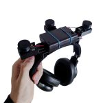
Normally getting the position of a person is pretty straight forward using a Kinect, but also getting the orientation of the person is a bit more tricky. In order to do this we developed the code resources included in this tutorial, and a headgear that could be mounted on a set of over-ear headphones. The headgear has three IR LEDs pointing up, making them visible for a IR camera to track.
-
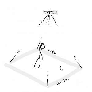
- Tracking area overview
-

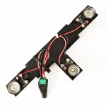
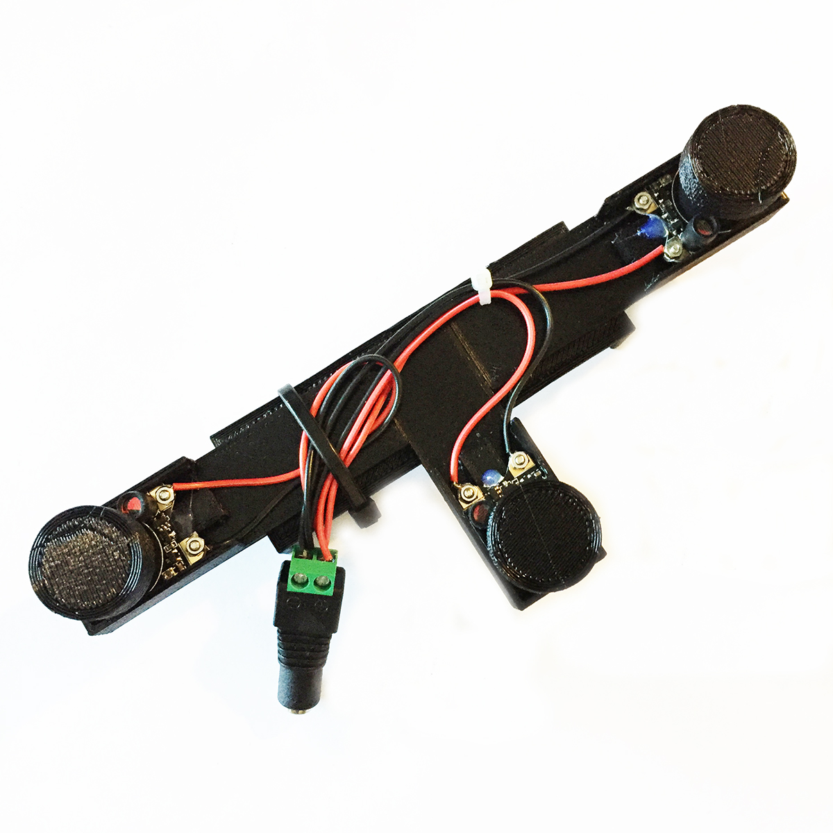
- Finished headgear

The strategy for tracking the orientation is based on finding these three light dots in the video input and calculation the orientation angle based on their relation to each other. The way of finding the position is a simple as using the (x, y) position of one of the dots found during the orientation calculation.
This tutorial is in two parts:
- Part 1: overview and explanation of main features of the tracking code.
- Part 2: adds a live Kinect input, and explains how the headgear is made.
Requirements
OS
-
- This project was developed on a Mac running OS X 10.15.2, and the Kinect resources used are Mac only. It is definitely possible to implement this project on other platforms, but you will need to be able to make the needed Kinect implementation and code changes yourself.
Software
Hardware
-
- a Kinect v1
- 3 x IR LEDs (we used a module meant for Raspberry PI IR cams)
- 2 x AA batteries (we used a NI-MH, rechargeable, 2600mAh)
- A battery pack for connecting 2 AA batteries in series (we used one with a on/off switch for convenience)
(Optional)
-
- 3D printer (to make a mounting brace for the IR LEDs)
- Headphones (the IR LED mounting brace was designed to add on top of a set of standard on-ear headphones)
Part 1: The tracking code
This part uses input from a video file recorded with a Kinect while filming our IR LED headgear. This is in order to focus on getting to know the code, before adding the complexity of custom made hardware, and a different tracking environment.
After making sure you have installed the Processing IDE and have installed the video library into Processing, you need to download the tutorial resources from this GitHub folder: https://github.com/airlabitu/Tutorials/tree/master/Orientation_and_position_tracker
Then find and run the Processing sketch called Orientation_and_rotation_video_file. You should now see something like this…
![]()
This is showing a video recording of our IR LED headgear moving around, with the tracking information as a visual overlay. This recording was made with the Kinect’s IR cam, and will be replaced by a live Kinect input in part 2 of this tutorial.
Now to the code…
Code overview
The code is divided in three files. The main file with the same name as the Processing sketch, including the Processing native setup and draw functions, and two other files with classes handling the tracking. The tracking is done with a technique called blob detection. The class you will be handling from the main file is the one called “Tracker”. This class is looking through the video input (video file in this case), searching for exactly three light blobs (bright areas). When that is found it starts to examine them to calculate orientation and rotation of the headgear.
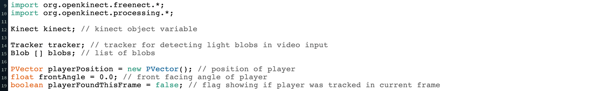
Declarations
The main thing here in the top of the code is the declaration of the Tracker object in the variable “tracker”.
![]()
Setting up the “Tracker” object (setup)
In setup the features of the Tracker is set. Depending on the quality of your input source, and how well the lights stand out from the background you will need to fill out more or less of these features. They all have default values which you can find in the Tracker class code. The greyed out lines are not needed while using the example video here in part 1, but will be nice to know going into part 2 of this tutorial, where you will be using your own hardware and tracking space.
![]()
Running the Tracker object (draw)
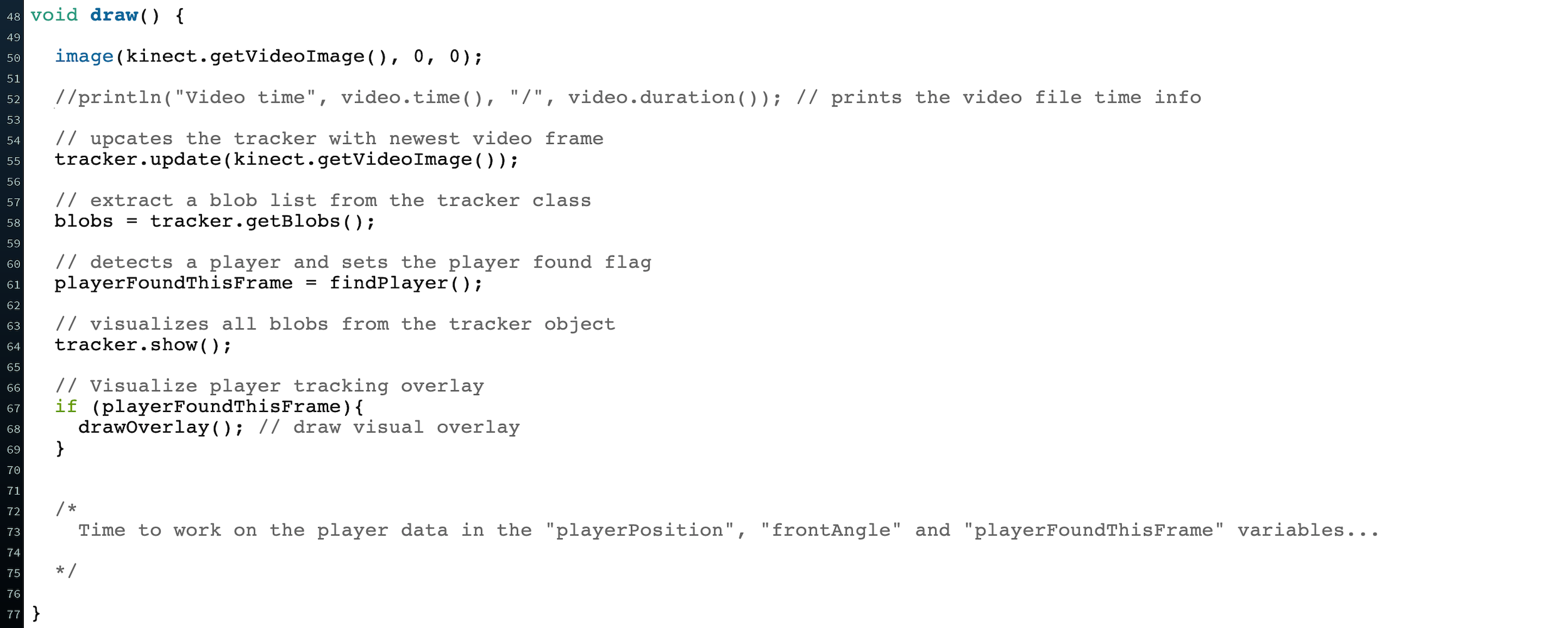
After loading the current pixels into the video object and handling the video looping we get to the actual handling of the Tracker class.
The following three steps are always needed for the tracker class to work.
-
- Update the tracker object by passing the current video frame through the tracker.update() function.
- Extract the blobs from the tracker object with the tracker.getBlobs() function.
- Search for the three light dots on the headgear with the helper function findPlayer().
After this the result is visualised. It is also here you can start writing your own code using the tracking information in the global variables: playerFoundThisFrame, playerPosition, frontAngle.
![]()
Helper functions
The remaining code in this file are helper functions used to find the three light dots on the headgear, and calculating the orientation and position of the person waring it. Not something you need to look closer into, unless you wish to alter how this part works…
PART 1 done 🙂
PART 2: The headgear & live Kinect input
For this part you need the resources found in the two folders Headgear and Orientation_and_rotation_kinect from the downloaded resources.
Assembling the headgear
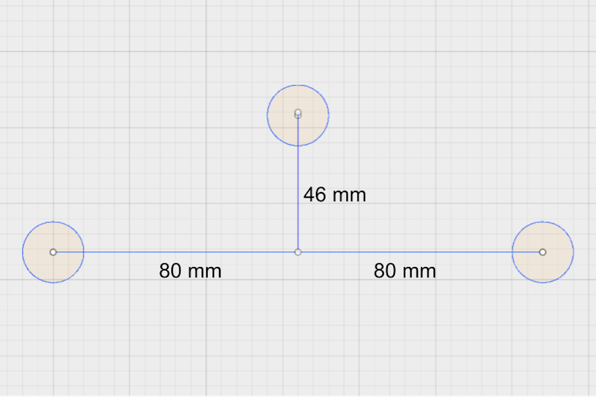
Start by either 3D printing the parts found in the Headgear folder (Headgear -> 3d_parts), or make your own rig where the placement of the IR LEDs follows the drawing IR LEDs placement.
-
- 3D print parts

-
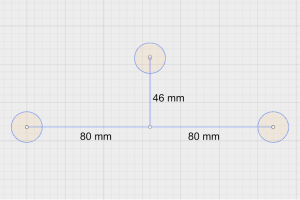
- IR LEDs placement
OBS: depending on your printers printing quality and settings you might need to increase/decrease the thickness of the diffuser caps.
After printing the parts (or making your own rig) you need to assemble the headgear:
- Glue the parts together.
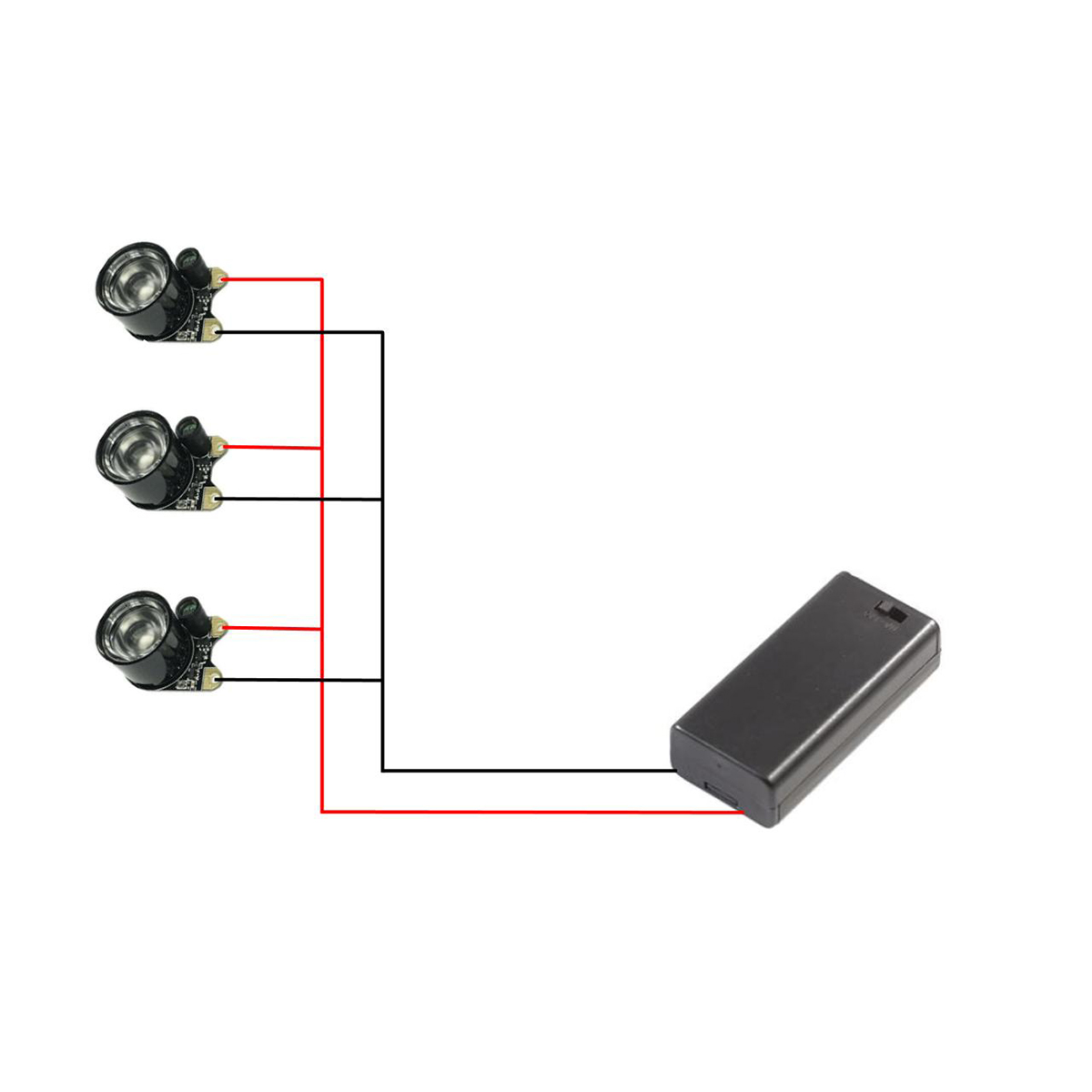
- Attach wires to the IR LEDs (see: headgear wiring schematics).
- Add the leds to the headgear (tag glue for easy removal until everything works well).
- Add the diffuser caps to the IR LEDs (tag glue for easy removal until everything works well).
- Add the battery pack.
- Connect the battery pack and the IR LEDs (see: headgear wiring schematics).
- Add the headgear to the headphones (we used cable ties and rubber bands, in order to make it easy to remove again).
-
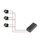
- Headgear wiring
-
- Headgear with LEDs

-

- Headgear with LED caps
-
- Finished headgear
Live Kinect input
In the following section we will add the Kinect to the code for live input. This will allows us to test if the headgears IR LEDs are working, and see how the Tracker settings in the code perform in your setup.
For the following you need to install the Processing library “Open Kinect for processing” and restart Processing.
Setting up the Kinect
First step is to modify the Kinect a bit. The Kinect is normally used for measuring the depth of each pixel. It does this by projecting an IR grid (left lens), and the analysing it with the IR cam (right lens). This projection is distorting the image quality of the IR cam, so we are going to block it since we are not going to use the depth map anyway. We used simple paper tape, that is easy to take off again, and doesn’t leave sticky surfaces afterwards.
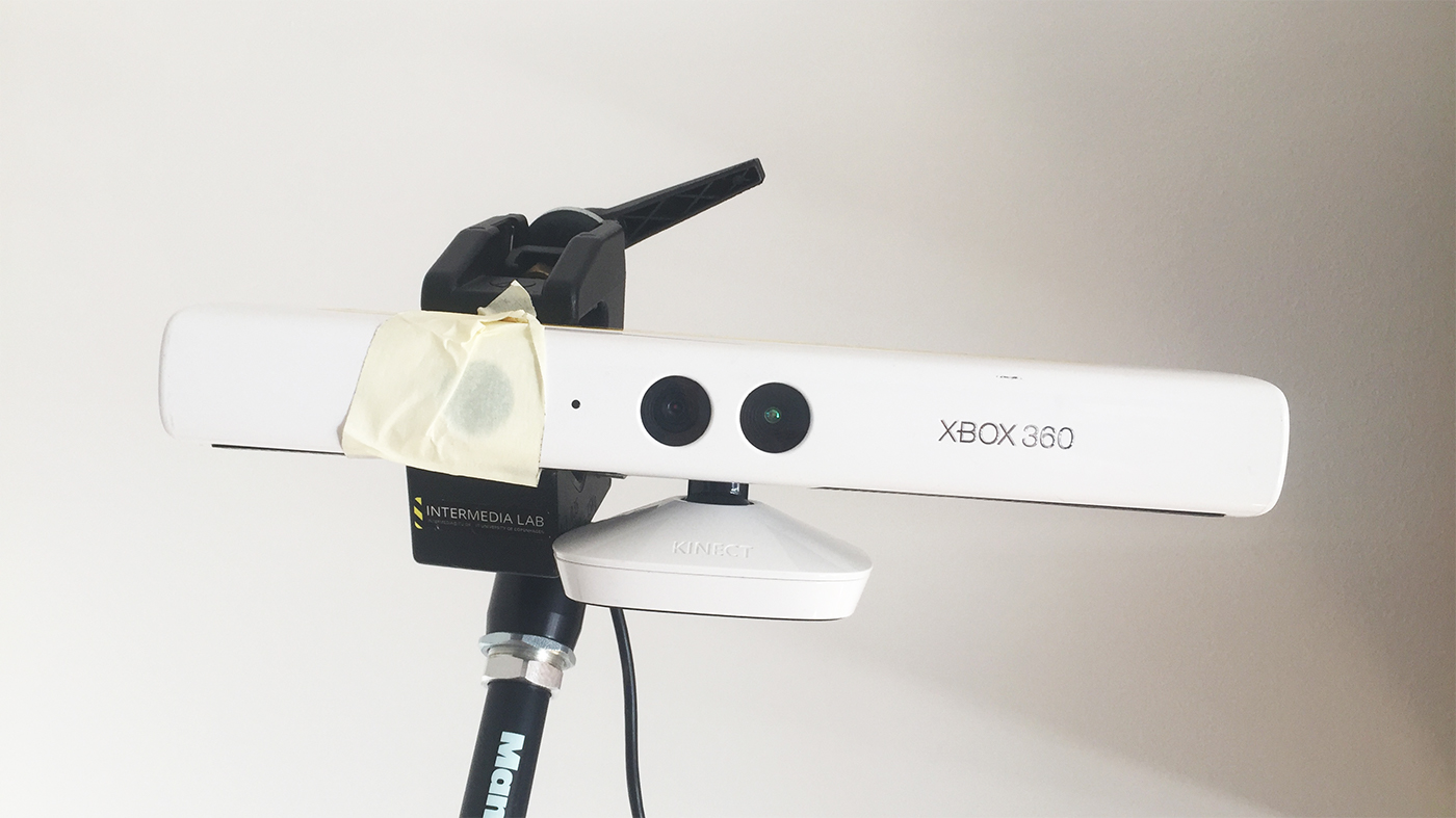
Kinect with blocked lens
Now do the following in order to test if the Kinect works as intended.
- Connect the Kinect power supply to a socket, and insert the USB cable in your computer.
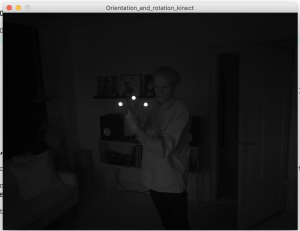
- Run the Processing sketch from the resources folder called Orientation_and_rotation_kinect.
- After a little wait the sketch should fire up and you should see the IR cam view from the Kinect.
Kinect IR cam image
The image should be pretty dark, as on the image above. This is because there should be very little infrared light for the camera to see. A condition we need to make sure the IR LEDs on the headgear will stand out as the brightest points, when we start the tracking.
If this is not the case you can try the following:
- Limit the natural light in the tracking area (roll down curtains),
- If this is still not enough try to turn off synthetic light, since some light bulbs etc. also sends out a bit of IR light.
Testing the setup
Now you hopefully have a pretty dark IR image. Then turn on the battery pack on the IR headgear and bring it in front of the camera. Depending on your tracking conditions you should now see one of the two following types of screens.
-
- SCREEN 1
-
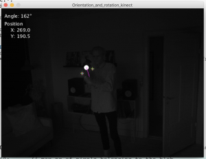
- SCREEN 2
If you get something like the SCREEN 1 (left) you need to adjust the “Tracker” settings in the code.
Before looking into that just a brief overview of the changes in the code from PART 1. We will not run through all code changes, but just briefly explain how the Kinect was implemented.
Kinect code implementation
As you see in the top of the code we are now using the Kinect library instead of the Video library. The changes we have made are therefore rather simple. Where we before used the variable “video” storing the Video object we now use the “kinect” variable, storing the Kinect object. And of course removing all code that related to playing the video file.
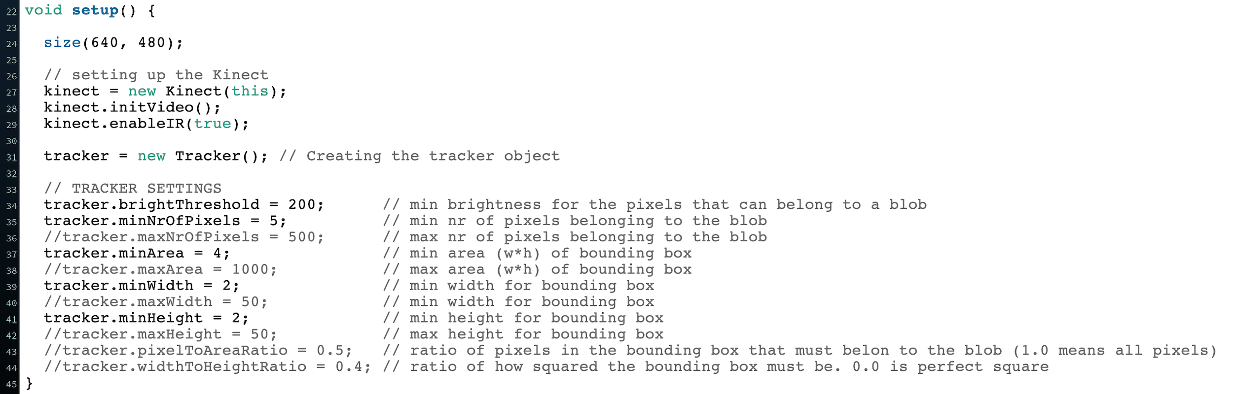
Adjusting the Tracker settings
As you saw in PART 1 the Tracker object has an area in setup where we can override the default values and fit the tracker to our tracking conditions.
![]()
The first setting to try is to adjust the brightness threshold. I must be a value between 0-255.
If you are not tracking anything after that it might be a good ida to set the different min settings.
If you instead are tracking other things than 3 dots, you can use the max settings to filter out the unwanted blobs.
The two ratio settings pixelToAreaRatio and widthToHeightRatio are useful if you either are tracking something else than the LEDs with a low amount of bright pixels inside the bounding box, or something that is not at all squared, as the LEDs bounding box should be.
Hopefully you are now fully up and running with this setup and ready to use it for your own creative purposes.
Please send us links to your projects, we would love to see where it goes from here 🙂 … and remember to credit (Halfdan Hauch Jensen, halj@itu.dk, AIR LAB, IT University of Cph)